Author: Ben Lewis
Introduction
High-density polyethylene (HDPE) geomembranes are critical components of modern landfill lining systems, providing an impermeable barrier to contain waste and protect the environment. To meet stringent engineering demands – such as slope stability, strain tolerance, and long-term durability – designers often specify textured HDPE geomembranes rather than smooth sheets.
Textured liners greatly improve interface friction against soils and geosynthetics, enhancing stability on landfill slopes. However, not all textured geomembranes are equal. This white paper evaluates the advantages of structured embossed texturing produced via flat-die extrusion versus traditional blown film (spray or coextrusion) texturing. The focus is on landfill applications (as guided by Australian Best Practice Environmental Management guidelines), with relevance to other containment uses (mining tailings storage, wastewater ponds, etc.). The goal is to present a technical comparison for engineers and specifiers, demonstrating how structured-textured HDPE liners can improve performance and potentially reduce costs in landfill projects.
Landfill Liner Design Requirements and BPEM Guidelines
Landfill lining systems must maintain integrity under a range of stresses. Liners are subject to settlement of underlying waste, thermal expansion, construction loads, and hydraulic pressures. Strain tolerance is therefore a key design parameter – the liner must accommodate movement without puncturing or stress cracking. The Victorian Best Practice Environmental Management (BPEM) guidelines for landfills emphasise limiting strains in geomembranes to prevent stress cracking and failure. While HDPE can elongate over 700% in laboratory tensile tests, in the field it experiences multi-axial strain conditions that significantly lower safe strain limits. For example, some regulators impose a mere 1% allowable strain in HDPE liners, and German standards (BAM) limit global strain to 3% with local strain under 0.25% to avoid stress concentrations. Such low-strain allowances necessitate heavy protection layers (cushion geotextiles or sand bedding) to prevent any sharp object or differential settlement from imparting high point loads.
Textured geomembranes are often used in landfills to improve the factor of safety against slope failure. A textured surface increases the interface friction angle between the liner and adjacent materials, reducing the risk of the liner or cover soils sliding, even on steep side slopes. In fact, a high-density textured liner can achieve interface friction angles on the order of 20-35°, enabling much steeper slope designs than would be possible with smooth liners. The BPEM guidelines acknowledge the role of textured geomembranes in providing adequate friction on side slopes and preventing cover soil slippage. At the same time, BPEM warns that certain texturing methods can compromise a liner’s tensile properties – thus, designers must balance friction gains against potential strain capacity losses.
Strain Tolerance and Cushioning Requirements
One specific guidance in the BPEM landfill guidelines is the allowable strain for different geomembrane types and textures. Notably, HDPE geomembranes with structured (embossed) texturing are allowed the same design strain as a smooth sheet (≈6% in strain) because the texturing process does not weaken the material. In contrast, HDPE with random spray or coextruded texturing has a lower allowable strain (≈4%).
Table D2 of the BPEM (citing Peggs 2003) shows that a structured-profile HDPE can be designed for ~6% strain, whereas a randomly textured HDPE is limited to ~4%. In practical terms, this means a structured-textured liner can accommodate greater deformation without risk, aligning with the performance of a smooth liner. This higher strain tolerance can be leveraged in two ways:
Reduced Cushion Requirements: If the geomembrane can safely handle more strain, the designer may specify a lighter-weight protection geotextile or thinner soil padding while still keeping the liner’s strain below the allowable limit. A structured-textured HDPE liner, being more forgiving strain-wise, does not rely as heavily on extremely heavy cushion layers to prevent localised strain exceedance. This can yield cost savings in material and installation without sacrificing safety. For example, whereas a coextruded textured liner might require a very thick nonwoven geotextile (or sand layer) to limit strains under point loads to <4%, a structured-textured liner could achieve acceptable strain with a moderate geotextile since ~6% strain is tolerable. Reducing the cushion layer (while still protecting against puncture) also brings the liner into closer contact with the subgrade or geosynthetic clay liner (GCL), which can improve interface shear performance.
Improved Safety and Interface Performance: Alternatively, designers can keep the same robust cushion and take advantage of the structured liner’s higher strain capacity to provide an additional factor of safety. The liner will then experience even lower strain in service, well below its 6% limit, greatly minimising the chance of stress cracks over decades of loading. Maintaining low strain also helps the liner remain intimate with the subgrade (avoiding void spaces) and can optimise interface friction. A thick cushion geotextile sometimes creates a “softer” interface that can slide or deform; if a slightly lighter cushion is feasible due to higher strain tolerance, the contact between the textured liner and surrounding soil/geosynthetics may be more direct and interlocked.
In either case, the structured texture provides confidence that the liner’s elongation capacity is not the weak link in the design. Engineers can thus meet or exceed BPEM strain criteria with more flexibility in how they design the protective layers.
In summary, the BPEM guidelines drive home the importance of strain control for HDPE liners in landfills. Structured embossed texturing directly addresses this by delivering a textured HDPE geomembrane that performs on par with a smooth sheet in terms of tensile strain capacity. The following sections will delve into how the manufacturing methods behind different textures lead to such differences in performance, and what other benefits the structured approach offers in landfill applications.
HDPE
Textured HDPE geomembranes can be manufactured by different processes. The two primary categories are:
Blown Film Texturing (Coextrusion or Spray Methods) – a textured surface is produced during or after extrusion by creating a random roughness on the sheet.
Flat-Die Embossed Texturing (Structured) – a patterned surface is moulded or pressed onto the sheet during flat-die extrusion.
Understanding these methods is important because the texture formation affects the geomembrane’s thickness uniformity, mechanical properties, and surface consistency. Below is an overview of each approach and its implications:
Blown Film Coextrusion Texturing
Traditional textured HDPE liners are often made on a blown film extrusion line with a circular (annular) die. In a typical coextrusion process, molten polyethylene is extruded in three layers: a core layer sandwiched by textured outer layers. A blowing agent (often nitrogen gas) is introduced into the outer layers as the extruded tube is expanded. As the nitrogen escapes and the polymer cools, it disrupts the surface, forming a random rough texture of peaks and valleys. This method essentially “froths” the surface, creating a sandpaper-like finish. The resulting texture is monolithic (fused to the liner) but inherently irregular. Manufacturers can adjust parameters like gas injection rate to change the asperity height of the texture, but the texture pattern remains random in distribution.
An alternative variant is the spray-on texture. In this two-step method, a smooth geomembrane (produced by blown or flat extrusion) is post-treated by spraying molten polymer droplets onto its surface. The splattered droplets solidify into a rough, granular texture. This also creates a random surface profile, and the texture thickness can be adjusted by spraying more or less material.
Blown film and spray texturing processes succeed in producing high-friction surfaces, but they come with several drawbacks:
Variable Thickness and Mechanical Properties: The coextrusion of textured layers can lead to non-uniform core thickness. The peaks of the texture may effectively thin out the sheet in those areas, or create micro-voids, reducing the cross-sectional area that carries load. Consequently, coextruded textured liners often show reduced tensile strength and a lower elongation at break compared to smooth sheet. The texturing introduces micro-notches and imperfections that act as stress concentrators. Over time, these can initiate environmental stress cracking under sustained load and chemical exposure. As one industry paper notes, the tensile strength and strain to rupture are diminished in blown-film textured HDPE due to the notches caused by the process. Designers must account for this reduction – for instance, the BPEM recommends a lower allowable strain (4%) for randomly textured HDPE vs 6% for smooth. In practice, manufacturers often increase the base sheet thickness or specify a minimum asperity height to compensate, but the inherent material efficiency is lower.
Inconsistency of Texture: Blown film texturing is known to produce high variability both across a single sheet and between production runs. The texture density and height can fluctuate, meaning the interface friction performance might differ from one roll to the next. Sieracke (2005) famously questioned this inconsistency: “What good is direct shear testing if the material provided is not consistent with respect to texturing?”. From a quality assurance standpoint, this variability is problematic – extensive sampling may be required to ensure the delivered rolls all meet specification for asperity height and friction angle. It is also challenging to reliably predict slope stability if the liner’s interface properties are not uniform.
Thickness Measurement and CQA Challenges: The irregular profile of a coextruded or sprayed texture complicates field quality control. Defining the “thickness” of a textured geomembrane can be ambiguous – is it the peak-to-valley thickness or the nominal core thickness? ASTM D5994 provides a method to measure textured geomembrane thickness using micrometres, but results can vary depending on whether the measurement happens on a peak or in a valley. The BPEM document notes debates in CQA over how to determine thickness for non-uniform textured sheets. In contrast, smooth edges (if provided) and consistent texture make it easier to verify thickness compliance. Blown film liners may also exhibit fold lines from the collapsing of the blown bubble, which can lead to slight wrinkles or weaker zones in the sheet. These fold creases and occasional gel or unmelt inclusions (from the extrusion process) can introduce pinholes or thin spots in blown film geomembranes, requiring careful inspection. All these factors mean CQA for randomly textured liners must be especially vigilant.
Installation Difficulties (Hooking and Curling): The very rough, aggressive surface of a coextruded or spray-textured geomembrane can create a hook-and-loop effect when placing geotextiles or GCLs against it. The fibres of a nonwoven geotextile can snag on the sharp asperities (akin to a Velcro® hook side grabbing fabric). This “sticking” is beneficial for increasing friction, but during installation, it makes it difficult to slide or reposition a geotextile or drainage geocomposites once it contacts the liner. Installers sometimes must lay a thin slip sheet or employ extra workers to ensure a geotextile can be properly positioned without pulling or stretching on the liner beneath. Additionally, blown-film textured sheets can exhibit more memory and curvature from being wound in rolls, which reduces their lay-flat behaviour. Especially on a hot day, a textured liner with uneven thickness might not relax evenly on the subgrade, leading to more wrinkles that have to be managed before covering. These handling issues add time and effort in the field.
Despite these drawbacks, blown film and spray-on texturing have been widely used for decades and can perform adequately if properly manufactured and tested. They generally cost less to produce than flat-die embossed liners, since blown film extrusion is high-throughput and simpler to calibrate. Manufacturers have also improved coextrusion control to mitigate some variability. Nonetheless, the above issues have driven the search for a better texturing method – which leads to structured geomembranes.
Flat-Die Embossed “Structured” Texturing
Structured texturing is an alternative manufacturing approach that yields a regular, engineered pattern on the geomembrane surface. In this process, the HDPE is extruded through a flat die (also called cast extrusion or calendaring) to produce a continuous sheet at the full final width. While the polymer sheet is still hot and malleable, it passes between rotating embossing rollers that imprint a predefined pattern (such as truncated cones, spikes, or studs) onto one or both sides of the sheet. The texture is thus moulded into the sheet in a single continuous process, bonding integrally without secondary steps. Figure 1 below shows a close-up of a typical structured HDPE geomembrane surface with uniformly distributed conical asperities moulded in:
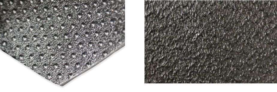
Figure1: Structured HDPE geomembrane surface with uniform embossed texturing (regular asperity pattern on left and Nitrogen blown texture on blown film HDPE on the right.
Because the embossing rollers are precisely machined, the resulting surface profile is highly consistent in asperity height, shape, and spacing. Common patterns include closely spaced small cones or spikes (for general applications with geotextiles and soils) and larger stud or nub patterns (for specialty cases like integrated drainage layers). The key characteristic is that the core thickness of the sheet remains uniform – the valleys between asperities are essentially the same thickness as a smooth geomembrane, with the texture adding extra material above the surface. The embossing does not stretch or thin the sheet; it simply redistributes some polymer into raised structures while the sheet is in a semi-molten state. As a result, mechanical properties are not compromised. The flat-die structured geomembrane’s tensile strength, puncture resistance, and elongation are comparable to those of a smooth geomembrane of the same nominal thickness. One publication notes that with flat-die embossing, the geomembrane’s tensile and elongation properties are “closer to the values of smooth sheet” because no weak spots or major thickness variations are introduced. This is reflected in design standards: structured-profile HDPE is permitted a higher allowable strain than random textured HDPE (as discussed earlier) – effectively regaining that ~50% margin of strain capacity.
Some advantages of the structured embossing method include:
Uniformity and Reliability: Since the texture pattern is the same from edge to edge and roll to roll, engineers can rely on consistent interface properties. A structured-textured geomembrane provides “consistent and reliable interface shear properties from roll to roll and within a roll”. There are no surprise slick spots or overly aggressive patches – the friction angle measured on one sample will be representative of the entire shipment. This uniformity greatly aids design confidence and construction quality assurance (CQA). For example, conformance testing can be done on a few samples, knowing that the production process inherently limits variability. In contrast to coextruded products, there is less concern that the delivered texture might differ from the tested samples. Thickness is also consistent, eliminating debates over measurement: the core thickness is well-defined and the asperity height can be separately specified (e.g. 0.5 mm average). The structured liners meet the standard asperity height requirements (often ≥0.25 mm per GRI GM13) with a controlled, measurable pattern.
Preserved Mechanical Integrity: Embossed texturing avoids the creation of micro-cracks or voids in the polymer. No inert gas bubbles are used, and no secondary spraying is applied, so the sheet is solid and fusion-bonded throughout. This means the HDPE’s intrinsic properties – like yield strength, break elongation, and stress crack resistance – remain at their highest levels. Independent studies and industry data have shown that an embossed HDPE geomembrane does not suffer the reductions in tear resistance or multi-axial tension performance that a coextruded textured one does. For instance, environmental stress crack resistance (ESCR) tests on structured-textured HDPE show performance equal to smooth sheet, with no influence from the texture. Manufacturers of structured liners report stress crack resistance values far exceeding the standard 500-hour requirement (often several thousand hours in ASTM D5397 SP testing), indicating a very robust material not prone to brittle failure. The Victorian BPEM explicitly lists HDPE structured-profile geomembranes as having a higher allowable strain and implies they are less susceptible to stress cracking issues. All of this translates to a liner that can endure long-term settlements and stresses with a larger safety margin.
Enhanced Interface Friction with Different Surfaces: Embossing technology allows tailoring of the texture on each side of the geomembrane. This is a unique benefit – for example, the liner’s bottom side could have a more aggressive spike texture to grip a geotextile or clay layer on a steep slope, while the top side could have a moderately rough texture or even integrally formed studs to facilitate drainage and protect the liner from puncture. Such dual-surface customisation is difficult with blown film methods. By optimising the texture for each interface, one can maximise friction where needed and even eliminate separate components (one structured product can simultaneously act as a liner and a drainage layer in a final cover, for instance). In general, the interface shear performance of structured geomembranes is excellent. Studies have found that “embossed surface textures exhibit higher interface shear strength and lower post-peak strength loss” at the normal loads typical in landfill covers. Unlike some coextruded textures that can “comb over” or flatten under load (leading to a sharp drop in post-peak strength), the stout embossed asperities maintain engagement with the opposing material during large displacements. This yields a more ductile, reliable shear resistance, which is beneficial in maintaining slope stability even after initial movement. With structured spikes, interface friction efficiency with nonwovens or soil often exceeds 90% of the material’s internal strength, essentially approaching the point where the failure will occur in the soil or geotextile rather than at the interface.
Improved Constructability and Handling: From an installer’s perspective, flat-die geomembranes are known for their excellent lay-flat characteristics. The manufacturing process produces a flat sheet with no folded memory; when unrolled on site, the liner lies relatively flat against the subgrade. This helps in avoiding wrinkles and “fish mouths” (buckles) during placement. While no HDPE liner is completely wrinkle-free under temperature changes, the structured sheets tend to have less inherent curvature and can be placed more smoothly. Additionally, the texture profile of embossed liners, while providing friction, is typically easier to work with during installation. The asperities are often rounded or conical rather than very jagged, which mitigates the hook-and-loop sticking problem. Geotextiles can be deployed over a structured liner with less snagging, allowing installers to reposition or tension the geotextile as needed. One publication noted that “Embossed geomembrane surfaces, on the other hand, allow positioning of geotextiles and geocomposites without major difficulty” as compared to coextruded surfaces. This can speed up installation and reduce the risk of accidental liner shifts or high local stresses caused by dragging materials. Most structured geomembranes are also produced with smooth edges (typically a ~100 mm margin along each side of the roll) to facilitate wedge welding of seams. The absence of texture in the weld area means the seaming process is identical to that of smooth HDPE – yielding high-quality, high-strength welds with less chance of leak paths. Contractors appreciate this because it avoids the need for grinding off texture or using special welding techniques; it also ensures that vacuum spark testing or air channel testing of seams is straightforward. The resulting seam peel and shear strengths easily meet GRI GM19a requirements since the sheet’s core properties are intact. All these factors improve the constructability and CQA of the liner system.
Long-Term Durability: A primary reason HDPE is chosen for landfill liners is its exceptional durability (chemical resistance, UV resistance, and resistance to oxidation). Structured-textured HDPE geomembranes continue this tradition. The flat-die extrusion with controlled cooling and calibration often results in a liner with lower residual stress and a more crystalline, stable polymer structure. Combined with high-quality resin and antioxidant packages, these liners show outstanding longevity. For example, flat-die manufactured geomembranes have achieved some of the highest standard oxidation induction time (OIT) and Stress Crack Resistance (SCT) values in the industry, indicating strong oxidative and cracking resistance. By not introducing micro-defects, the structured texture ensures there are no initiation points for oxidation or stress cracking apart from what a normal smooth sheet would have. Over decades, this means less risk of crack initiation under thermal cycling or chemical attack. In landfill environments, HDPE liners may be exposed to leachate chemicals, microbes, and stresses that can cause slow crack growth if the material is vulnerable. The structured liners, with their preserved stress-crack resistance (as demonstrated by multi-thousand-hour ESCR tests), are well equipped to withstand these conditions. In essence, one gets the best of both worlds – the durability of a smooth HDPE and the functional benefits of a textured surface.
Summarising the above, structured embossed HDPE geomembranes offer a suite of engineering advantages rooted in their manufacturing method. The texture is consistent and non-damaging to the material, resulting in super strain capacity, interface performance, handling, and durability. The next section will directly compare performance aspects that matter in landfill design, providing further evidence and context for these benefits.
References
• Victorian EPA (2015). Siting, Design, Operation and Rehabilitation of Landfills (Landfill BPEM), Publication 788.3 – Appendix D: Liner and Capping Systems (Table D2: Allowable Strains).
• Peggs, I. (2003). Geomembrane Liner Durability: Contributing Factors and the Status Quo. (Referenced in BPEM for allowable strain guidance).
• Richardson, G.N. & Thiel, R. (2001). “Interface Shear Strength: Part 1—Geomembrane Considerations.” Geotechnical Fabrics Report, 19(5):14-19. (Discusses interface friction issues with various geomembranes).
• Stark, T.D. & Richardson, G.N. (2005). “Slope Stability of Final Covers.” Geosynthetics, 23(6): 26-33. (Notes on post-peak shear of textured geomembranes).
• Geosynthetics Magazine (2007). “Using structured geomembranes in final solid-waste landfill closure designs.” (Geosynthetics, Feb 2007) – G.L. Hebeler et al. (Highlights manufacturing and performance differences of structured vs coextruded geomembranes).
• Solmax (2021). How can textured geomembranes be used in waste landfill designs? (Blog article by S.J. Hao & D. Sutherland, Jan 2021) – Comparison of coextrusion, spray-on, and embossed texturing, and their interface friction outcomes.
• Atarfil (2023). Product Data – Atarfil HD Textured (Flat-die structured HDPE geomembrane technical specification). (Demonstrates maintenance of elongation at break, smooth edges for welding, and high stress crack resistance in structured liners).
• Geofabrics Australasia (2023). Atarfil HD Geomembrane – Impermeable Barrier for Waste and Water (Product brochure). (Notes flat-die manufacturing yields high durability and consistency, meeting BPEM guidelines).